一、Battery pack program
537.6V60AH lithium iron phosphate group: 60AH monomer the battery (GLD P611120P 60Ah) 168 series.
二、Management system solutions
The power management system mainly consists of the following parts: data acquisition module, main control module (including current sensors) display form.
1, the data acquisition module
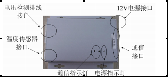
The data acquisition module and the battery pack is connected, Takeout temperature sensor, voltage, temperature, and other information for the acquisition of the battery pack. The set of power management system has 14 data acquisition module (an acquisition module 12 battery information) composed of the set of power management system with two temperature sensors. Another DC / DC from the battery pack on the collecting 12V power supply for the data collection module to provide working power (high power ancillary DC / DC module), it will be the acquisition of the battery voltage, the cabinet temperature and other information via the serial communication bus transmission to the master unit. Serial communication bus for data acquisition module and the control module communication medium.
Data acquisition module
Data detection module and battery pack connection diagram
1, the main control module
Master module functions as follows:
a data acquisition module communication battery pack voltage, temperature information
b, the current value of the measurement of the battery pack
c, real-time estimates of the remaining capacity of the battery pack
d, through the CAN bus and charging machine, motor controllers, communication, serial communication lines and data acquisition module communication, the battery pack charging and discharging control.
12V power for display
f, will be displayed by the LCD BUS data transmission to the display.
Master module interface
3, a current sensor
A current sensor of the present system is the Hall ring-opening the battery sensor, the current range of ± 100A, the current sensor can be connected to the output of the positive or negative electrode of the battery pack, a schematic diagram of two connection methods are as follows (note that the current sensor above the arrows pointing):
Current sensor connection diagram
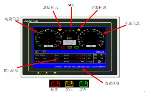
4 display
(1) Display 3.5-inch color touch screen.
(2) the entire structure of the touch screen of the display area, lights, power, communication port.
(3) the power of the touch screen and a communication interface required with the master module is connected, the connection diagram are as follows:
Touch screen connection diagram
(4) the operation of the touch screen status indicators include power (PWR), running (RUN), communications (COM) three lights. The touch screen is powered on when the power LED (PWR) is lit, bright green running lights. Touch screen CPU working running lights (RUN) is lit yellow, CPU fault, running lights (RUN) is not lit. When the connection BMS communication indicator (COM) is flashing yellow. As shown below:
Running indicator
Indicator Status Description
(5) using the instrument panel is displayed on the touch screen in the form of the values of the current, voltage, and remaining charge SOC. The form of numerical values at the same time the maximum current, the maximum voltage and the highest temperature value is displayed. By setting the area can be realistic single battery voltage, cell voltage in the display when the voltage values of the background color to indicate the battery status, Red: over-discharge; white: normal; Green: overcharge.
Display the main page
、
Monomer voltage display interface
Third, the charging conditions:
Charging voltage of 614V, charging current: 51A --- the fastest one hour to fully charge the battery.
Figure and size of the system overall effect (battery box + LCD display)
Battery box consists of two of the same size battery cabinet (one battery cabinet has no display, without distinction).
Size:560*450*1650mm


 Data detection module and battery pack connection diagram
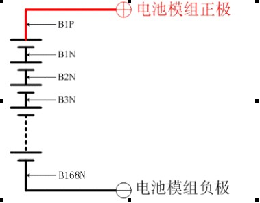 1, the main control module
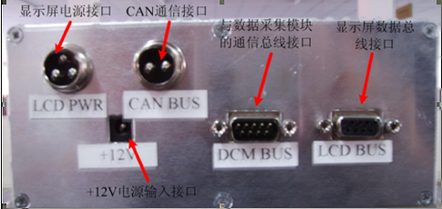 3, a current sensor
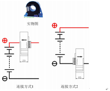 4 display
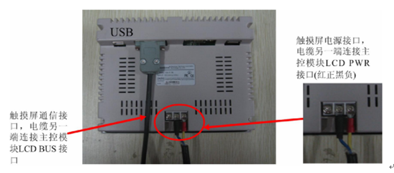 (4) the operation of the touch screen status indicators include power (PWR), running (RUN), communications (COM) three lights. The touch screen is powered on when the power LED (PWR) is lit, bright green running lights. Touch screen CPU working running lights (RUN) is lit yellow, CPU fault, running lights (RUN) is not lit. When the connection BMS communication indicator (COM) is flashing yellow. As shown below:Running indicator
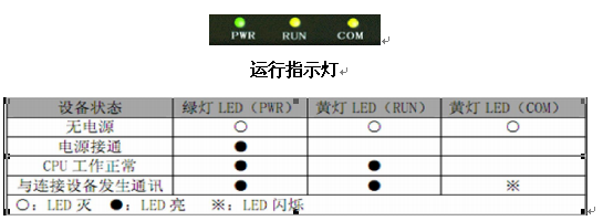 Indicator Status Description(5) using the instrument panel is displayed on the touch screen in the form of the values of the current, voltage, and remaining charge SOC. The form of numerical values at the same time the maximum current, the maximum voltage and the highest temperature value is displayed. By setting the area can be realistic single battery voltage, cell voltage in the display when the voltage values of the background color to indicate the battery status, Red: over-discharge; white: normal; Green: overcharge.Display the main page、
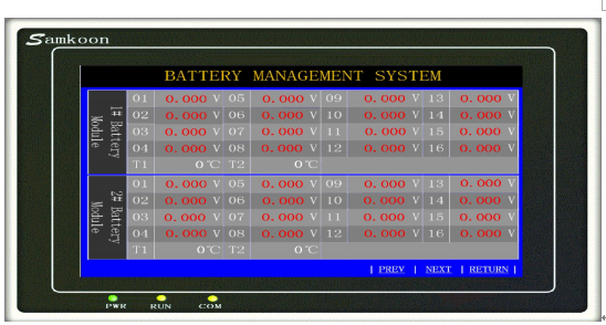 Third, the charging conditions:
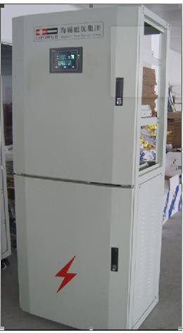 Size:560*450*1650mm